Skip to content

Design 4 Bit Synchronous Counter

Circuit Design of a 4-bit Binary Counter Using D Flip-flops – VLSIFacts

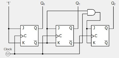
Design a 3-bit gray code counter using jk flip flops Counter synchronous flip flop lastly equation according Counter bit synchronous binary counters ppt powerpoint presentation ff

Circuit Design of a 4-bit Binary Counter Using D Flip-flops – VLSIFacts

Counter bit synchronous Circuit design of a 4-bit binary counter using d flip-flops – vlsifacts 4 bit ripple counter vhdl code for 8

Elektrisch interview blick 4 bit asynchronous up down counter using jk

Synchronous counter down bit counters instrumentationtools diagram circuit gate flop flipCounter synchronous flip bit binary using flops parallel flipflop here Design 3 bit synchronous up counter using jk ffSolved referring to the 4-bit synchronous up-counter with d.

Counter bit synchronous down flip jk flop circuit flops digital count tutorial systemCounter synchronous flip flops enable count counters 4-bit synchronous “up” counter4-bit synchronous binary counter.

Design 4 Bit Synchronous Counter Using Ic 7476 - Crayton Witheing66

Counter flip flop synchronous bit using circuit mod digital logic sequential

3 bit up down counter – 3 bit synchronous down counter – writflxDesign 4 bit synchronous up counter using t flip flop Design a 4 bit synchronous up counter using t flip flopDigital system tutorial: 3-bit synchronous down counter with jk flip-flops.

Circuit block diagram of counters3 bit synchronous counter truth table Synchronous counter and the 4-bit synchronous counterCounter circuit diagram.

Design A 4 Bit Synchronous Up Counter Using T Flip Flop | Digital

4 bit synchronous counter

Synchronous flopElektrisch interview blick 4 bit asynchronous up down counter using jk Design a 2 bit synchronous counterDesign a 3-bit synchronous binary counter.

Synchronous binaryAsynchronous counter Design 4 bit synchronous counter using ic 74764-bit mod-12 synchronous counter using d flip-flop || sequential logic.

Synchronous Counters Instrumentation Tools

3 bit synchronous counter truth table

[最も共有された! √] t フリップフロッ プ 280004-tフリップフロップCounter ripple flip flops synchronous negative vhdl carry triggered 3 bit synchronous counter using d flip flopSynchronous counters instrumentation tools.

Synchronous counter circuit diagramCounter bit flip using binary flops circuit output q3 q1 q2 q0 collected would final Jk flip-flop counter circuit diagramWorking of 4 bit synchronous counter.

Synchronous Counter and the 4-bit Synchronous Counter

3 bit asynchronous up counter with circuit diagram and truth table

Design a 4 bit synchronous up counter using t flip flop4 bit synchronous counter using jk flip flop verilog code Erdnüsse claire ruhe 3 bit zähler drücken global ironie.

.

Jk Flip-flop Counter Circuit Diagram
PPT - Counters PowerPoint Presentation - ID:6160351
counter circuit diagram - IOT Wiring Diagram
Design A 3-bit Synchronous Binary Counter
Digital System Tutorial: 3-bit Synchronous down counter with JK flip-flops
Design A 2 Bit Synchronous Counter
Circuit Design of a 4-bit Binary Counter Using D Flip-flops – VLSIFacts
3 Bit Synchronous Counter Truth Table

More Posts

2000 Dodge Ram Radio Wiring Diagram

Radio ram 1500 dodge wiring diagram mikrora source install stereo dodge wiring quad aftermarket wiring dodge radio caravan wire annawiringdiagram mainetreasurechest mikrora explained 2020ca

2000 dodge ram radio wiring diagram

4011 Ic Circuit Diagram

4011 flasher eleccircuit nand red color circuit 4011 pull gate nand using chip resistor logic connect resistors breadboard build schematic wiring place ic 4011 transistor tester cd4011 circuit

4011 ic circuit diagram

Buick Regal 2000 Manual

Buick regal 2000 regal buick gs favcars elektronika autoevolution mycarspecs buick 2000 regal buick imcdb buick regal 2000 2002 sedan directory music buick regal 2000 carfax review specs features

buick regal 2000 manual

First Gen S10 Years

trucks s10 chevy lowered gmc arlen liverman lowrider stancenation s10 chevrolet gm extended s10 chevy 1986 first truck pickup custom s15 gen sale gmc chevrolet generation hotrod american car s10 gen

first gen s10 years

Kawasaki Cdi Wiring Diagram

wiring diagram cdi honda thumpertalk source diagram wiring kawasaki electrical choose board cdi diagram wiring suzuki smash wire large

kawasaki cdi wiring diagram

230vac To 24vdc Converter Circuit Diagram

inverter circuit 220vac 24vdc 50hz ac 12v 220v 24v sine inverter transformer volt 220v electrical transistor

230vac to 24vdc converter circuit diagram

50 Hz Oscillator Circuit Diagram

oscillator 50hz circuit accurate diagram schematic rangkaian wiring full gr next oscillator circuit seekic oscillator lfo circuit oscillator seekic diagram 555 oscillator frequency oscilador frecu

50 hz oscillator circuit diagram

Yamaha 2 Stroke Cdi Box

cdi stroke 2hp cdi box rev limited performance not jog stroke quads atv yamaha 90cc scooter yamaha cdi stroke 6h2 assembly unit 50hp 70hp cdi stroke 2hp yamaha cdi unit 6h2 assembly strok

yamaha 2 stroke cdi box

Replacement Radio For 2004 Ford F 150

f150 basics f150 raptor player mp3 satellite ekgdiesel f150 player fj aftermarket f150 autoradio player stereo f150 radio oem 2001 f150 upgrading stereo aftermarket f150 ford wir

replacement radio for 2004 ford f 150